Thursday 23 March 2023

Ultralight Mesh Rack

Plastic meshes obviously become my favorite material for bicycle carriers.

After mesh handlebar bag and mesh under seat bag (see here), it's now time for
something bigger - a mesh rack. I hope it will be the revolutionary idea how to
carry your bicycle stuff with minimal weight containers. This front rack is made 
of a bit sturdier, 1 mm thick mesh. Its dimensions are 40 x 30 cm and is attached
at one end to the front tube or brake cables and at the other end to the old style 
Shimano derailleur cables which run outside the handlebar tape. Weight: 15 g. 
You just put the bag or small rucksack (up to 15 L) in it. maybe secured  by a 
piece of string. If you don't have Shimano style cables, attach any kind of cable
to the drops of the handlebar. 

On the other end of the bicycle you might attach something bigger - like a tent - 
under the seat and you're good for a RTW trip. I will show this set-up shortly.

Simple mesh rack ...


... with a bag in it.


... and with a 15 litre rucksack.


Monday 30 November 2020

Evolution of screw drivers

Some people believe that Darwin's teory of evolution of living organisms is one of the major corner stones of human civilisation. Richard Dawkins went even further and defined a "meme", the generalization of the gene, as the driving force of the evolution of morality in human society. 


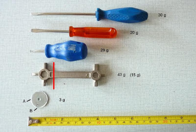
In this post we go a few steps back and consider the evolution of non-living things - namely screwdrivers. The evolutionary trend is - as should be expected from this blog - towards minimizing weight and size and maximizing simplicity. The first three screw drivers from the top in the picture need no further explanation. The fourth screwdriver is part of a multitool that was destined to be cut along the red line (reducing its weight to 15 g), but luckily it was spared that miserable destiny by the following consideration.

The fifth "screw driver" is actually a steel washer with the diameter 25 mm and thickness 1 mm. I filed it at the point A to produce a short flat part (not clearly visible in the picture) which acts as a flat screw driver. To be honest, this flat part is likely not even necessary. It works well with both flat and cross screw heads.

The cut in the washer at the point B serves a totaly different purpose: it is used when trueing a bicycle wheel with bladed spokes (Mavic Ksyrium wheels for example) to hold the spoke and prevent it from turning. This cut thus makes this washer-screwdriver a multitool - with 3 g probably the world's lightest bicycle multitool.  

Tuesday 30 June 2020

Ultralight tripod (for smart phones)

Strictly speaking, tripod should not be a part of an ultralight cyclist's luggage  - it's too awkward and heavy and there should always be a way to get away with improvisation. But, as we grow old, we realize that a small compromise is often more comfortable than strict principles. 

So here is my shameless compromise to a tripod for a smart phone. It's made of two clothespins, padded with pieces of cardboard. It weights 12 g. It should be useful when shooting self portrets on a bike or using long exposures. Not to mention that on a cycling tour clothespins can be used for their original purpose, to hang out something to dry or generally to pin something.

Clothespin "tripod" (actually a quadruped), front side.

Clothespin "tripod" (actually a quadruped), rear side.

The next episode of lightweight tripod is here. I resigned to the clothespins' tripod; it was too awkward to use, not very stable and too heavy (12g). The new version (4g) is here: take a plastic bottle, cut off a 3 cm strip from the middle part of it and cut two slots to hold your smartphone. I think this is the last step in the evolution of tripods and not even genetic manipulation could make it better.

Cut a part of plastic bottle


Make 2 slots in the plastics to hold the phone.

Thursday 14 February 2019

The ultimate wheel calculator


The usual, boring, spoke length calculators allow only the same number of hub holes, rim holes and number of spokes. What a waste of life and inteligence! This is a thing of the past. The times when it was important that a good bicycle wheel lasts few decades without breaking a spoke are definitely gone. The new trend is esthetics above functionality; and this requires to be able to build a wheel with any kind of combination of holes and spokes. This is where I jump in. What you will get here is a spoke length calculator (as well as wheel building motivator) for any number and combination of holes, spokes, cross patterns.

I’ll give more detail. Parts of the wheel are hub, rim and spokes. The hub has two flanges, left and right, each having half the total number of hub spoke holes. This also defines the left and right side of the wheel. The holes on the left and right flange are oset by an angle; if that wouldn’t be the case, we could not have radial spokes on both sides of the wheel. The spoke holes in the rim, however, are less obviously divided to left and right and it is important not to confuse the total number of rim holes with the number corresponding just to one side of the wheel. Further, spokes might be inclined out of the radial direction for some angle - this is usually expressed as a cross-number C, the number of spokes on one hub flange that a certain spoke crosses. Radial spokes don’t cross any other spoke, so they have cross number C = 0. When C is not 0 we might have two kinds of spokes on the same side of the wheel: leading spokes and trailing spokes. The first ones are inclined clockwise, the others counter-clockwise. And finaly, you might not want to (or could not) use all the holes in the hub or in the rim. We will consider all of these possibilities.
Figure 1. Schematical model of a Wheel.

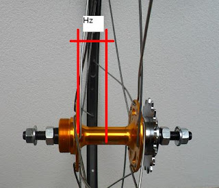
Figure 1 shows a wheel schematicaly. Point O is the center of the wheel. Line HR represents a radial spoke that goes through hole H in the hub and hole R in the rim and has inclination angles α = β = 0 to the x axis. If the effective rim radius is Rr = OR, and hub-hole radius is Rh = OH, then the length of radial spoke would be S0 = Rr - Rh. Line AB represents non-radial spoke. It’s starting inclination angle is α and ending inclination is β. Note that AB is a projection of the spoke to the plane xy. We have to take into account that spoke has a component in z direction. If Hz is a dimension from the hub flange to the center of the rim (figure 2), then the spoke length is straightforward to calculate:
       LAB 2 = (Bx − Ax)2 + (By − Ay)2 + Hz2 = R2 + R2 + Hz2 − 2RrRh cos (β − α)

Figure 2. Hub with indicated dimension Hz .
The unique way to describe a general wheel is to assign the starting hole in the hub A and the ending hole in the rim B to every spoke. We define the parameters of the wheel: Hh is the number of hub holes in one flange of the hub, Hr the total number of rim holes (i.e. all the holes in the rim), and S the number of spokes in one flange of the hub. With these parameters we build one side - left or right - of the wheel. Number of spokes on left and right side of the wheel might be dierent; if that is the case, we use notation Sl and Sr. For each spoke i , (i = 1, 2, ..., S) we note two indexes: the number of the hub hole Ai and the number of the rim hole Bi. We count hub and rim holes in a counter-clockwise direction starting at position β = α = 0 with hole number 1. Index Bi could have zeros, negative numbers, or numbers bigger then Hr when C > 1. This is OK when calculatig the spoke length, but for the hole count it is more practical to have only positive numbers in the range 1 to Hr; therefore we might add Hr to the zero or negative number and subtract Hr form numbers greater then Hr. Using notations ∆α = 2π/Hh and ∆β = 2π/Hr for angle segments in the hub and rim respectfully, we have the equation:

          Li 2= R2 + R2 + H2 − 2RrRh cos (∆β(Bi − 1) − ∆α(Ai − 1))

which defines spoke length for any spoke i and any possible wheel composition.
The key point is to define indexes Ai and Bi. We can define them individually, without calculation, ”by hand”. Automatism is, however, much appreciated, especially in later years of your life. That is why I wrote a program wheel that calculates indexes Ai and Bi, spoke lengths, draws a wheel and makes a finite element model for the calculation of stresses in the wheel.
Indexes Ai and Bi are calculated as follows. We would prefer the spokes to be equally distributed over the hub, with constant angle segment ∆γ = 2π/S. We first find Ai = j, i.e. a hole j in the hub which has the closest angle to the angle (i − 1)∆γ of i-th spoke:
                      Ai = MINj |(i 1)∆γ (j 1)∆α|,       j = 1, ..., Hh
In similar manner, we would find Bi = k:
                Bi = MINk |ϕ + (i 1 + (1)i+1C)∆γ (k 1)∆β|,      k = 1, ..., Hr
ϕ = π/Hh is the offset angle between the holes on the left and right flange of the hub. We must add this angle when calculating the right side of the wheel, but not for the left side.

Example 1. Let’s first give a simple example: the regular wheel. It has Hh = S = N = Hr/2, ∆α = 2π/N , ∆β = ∆α/2 and arbitrary cross number C. Spoke indexes are, in compact notation:  Ai = i  and  Bi = 2(i +(-1)i+1C) -1, and the dierence in the angles is:
                             ∆β(Bi − 1) − ∆α(Ai − 1) = (−1)i+1C∆α       
With numerical data for a 32-spoke wheel, Rr = 298 mm, Rh = 26, Hz = 20 mm and N = 32/2 = 16, we get spoke lengths (in mm) on one side of the wheel: 272.7, 274.9, 280.9, 289.7 and 299.8 for C = 0, 1, 2, 3, 4 respectfully. All the spokes on one side of the wheel have the same length. The other side of the wheel could have different spoke length, because of dierent dimension Hz or different C (figure 3).


Figure 3. 32-spoke wheel. Hh = 16, Hr = 32.  Left side 16 spokes, cross 2.  Right  side: 16 radial spokes. Wheel seen from the left side. Spokes on the left side are drawn with solid lines and with dashed lines for the right side. Blue for leading and red for trailing spokes. Rim and hub holes are numbered.
Example 2. Now, let’s present a more complicated case. I have recently built a rear wheel for my fixie with 32-hole hub, 36-hole rim and 16 spokes for the whole wheel, which means with parameters Hh = 16, Hr = 36, S = 8 (figure 4, left side). Not unexpectedly however, one spokes broke after about 200 km and another one after another 200 km.
I made a finite element analysis of the wheel with beam elements. Loading was 500 N vertical gravitational force and 250 N horizontal force in the chain acting on the edge of the hub. The stress analysis showed that the stress in the spokes was f =1.63 times greater than the stress would be in an ordinary 32-hole Wheel.
I experimented with different wheel parameters and as a first solution I added 4 spokes to the right side of the wheel (figure 4, right), which reduces the factor to f=1.17. The experiment is still on-going. I will ride with this wheel until possibly the next spoke breaks, and then decide about the new wheel configuration.

Figure 4. Fixie rear wheel, Hh=16, Hr=36. Left: 16 spokes. Right: 20 spokes.


Figure 5. My fixie. Both hubs have 32 holes. Front wheel: 24-hole rim and 16 radial spokes. Rear wheel: 36-hole rim and 20 spokes, mostly cross 2.